

Blog
MECHANICS OF VARIOUS BRAKE SYSTEMS
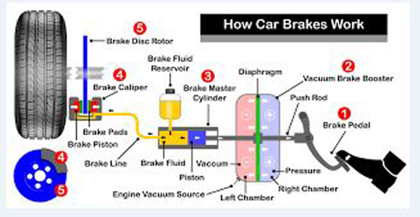
Overview of braking system
Before we delve into the detailed mechanics of the various brake systems that bring you safely to stop please be aware that there is no make or model of car that contains all of parts described below. There are variations of those parts described below.
These various systems need to be able to cope with varying speed, weight of passengers and loads, weather conditions and road conditions.
The manufacturers have designed some very sophisticated systems into your vehicle. They have documented all the specifications that need to be adhered to one cannot replace original parts unless the replace conforms to manufacture’s specifications.
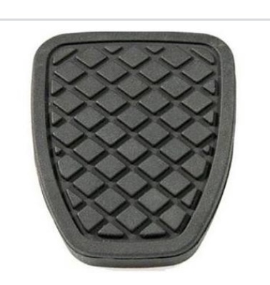
Brake pedal pad
This fits over the face of the brake pedal.
Purpose
The nonslip pad is to prevent the driver’s foot slipping of the pedal in wet weather.
Description
The brake pedal pad is normally made of non slip rubber. In some cases the pedal is a well finished metal with raised rubber semi convex attachments.
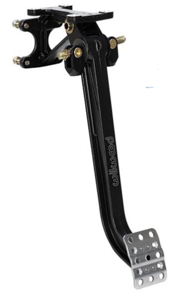
Foot brake pedal.
In Australia this is situated just to the left of the accelerator.
Purpose
As the pedal is depressed it activates the brake booster.
Description
It is hinged at its upper end onto the firewall, as the bottom portion as the rubber pad is depressed a metal rod passes through the fire wall of the cabin to the engine compartment where it connects to the brake booster.
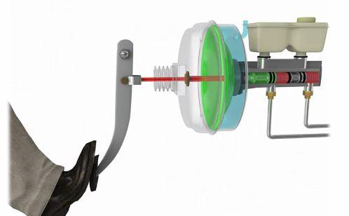
The Vacuum Brake Booster.
This is a sealed container which has an inlet port and an extraction port.
Purpose
This increases the pressure applied by the driver via the brake pedal to the brake master cylinder. The pressure that the driver is able to apply to the braking system is amplified many times. Even slightly built people have the ability to bring even heavy vehicles to a stop.
An alternate system to the vacuum mechanical brake booster is electronic activation of the brake booster. It should be noted that both of these systems do have manual backups.
Hybrid and electronic vehicles EV have regenerative braking systems which tend to extend the life of the brake pads and rotors.
Description
Direct Physical contact type.
The pressure that you apply to the brake pedal in your car needs to be amplified many times and distributed to the four wheels of your car.
The booster housing is made of metal, it is circular normally about 20cms in diameter, with opposing two open sides joined together at their outer rims. Internally it has a flexible diaphragm which is sealed to the outer edges of the body. This diaphragm moves backward and forward depending on the air pressure on either side of it. There is a metal rod running through the body from back to front. This rod is connected on the entry side to the brake pedal, on the opposite side or exit side it connects to the brake master cylinder.
When the brake pedal is not being depressed the brake booster intake valve is closed.
An air filter sits in front of the valve to ensure no dust particles enter the booster when the valve is opened. There is also a second valve which passes through the diaphragm. It works in synchronisation with the intake valve.
When the brake pedal is not depressed this diaphragm valve is open. As the air inlet valve opens the diaphragm valve closes. Now as the valve closes there is a pressure differential between the two sides of the diaphragm. The input side of the booster diaphragm has air at normal atmospheric pressure, and the other side is connected to either a vacuum pump or engine vacuum.
The central rod now moves forward activating the pistons of the master cylinder. As a fail safe mechanism there is a solid rod running for brake pedal to master cylinder. Should this not be the case and the diaphragm fracture one would have no brakes at all. With the metal rod in place one could still apply some force to the via the pedal to the brake pads.
Electronic hydraulic brake booster pumps
The pressure that you apply to the brake pedal in your car needs to be amplified many times and distributed to the wheels cylinders of your car.
This system too has a fail safe system.
Purpose
Electronic brake boosters. Purpose is the same as vacuum brake booster and are mainly used in vehicles which do not a vacuum and vacuum pump.
Description
Great care should be taken while working on the callipers of some vehicles when cars are fitted with electronic hydraulic brake booster pumps. As one opens the driver’s door of these models the electric current is connected to the pump to pressure prime it. The pistons can shoot of housing with huge potential damaging force.
Before starting on these cars take care. One needs to connect the on-board computer to deactivate this automatic facility and then reactivate it at the completion of the job before testing and driving the car.
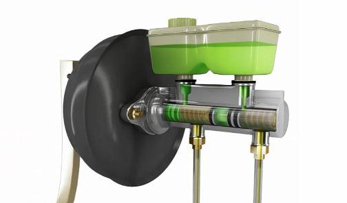
The Master Cylinder
The master cylinder, which is made of metal, sits immediately in front of the brake booster and beneath a plastic reservoir holding the brake fluid.
Purpose
The purpose of the brake master cylinder is to transform physical movement into hydraulic movement so that it can be easily transferred and distributed to the brake parts of the vehicle. At the final destination it activates the pistons in the brake callipers. A this point the pressure in the hydraulic transferred back to physical movement to push the calliper pistons against the brake pads and in turn against the surfaces of the rotors.
Description
The reservoir has a removable dust cover, a vertical divider within the reservoir, an outlet from each compartment to the pistons in the master cylinder. It has sensors warning of low levels of fluid in the reservoir which will give a warning signal on the dashboard.
There are generally two pistons in the master cylinder sitting one behind the other. When the brakes are not depressed the fluid in the reservoir can run freely into the piston’s cylinders. As the brakes are depressed these access ports to the reservoirs are sealed and the fluid in the cylinders compressed by the pistons. The harder one presses on the brake pedal, the greater the pressure in the fluid. This increased pressure is instantaneously present in the entire hydraulic system. The two cylinder system is a part of a fail / safe precaution. I one cylinder fails the other will still work and keep the braking system functioning.
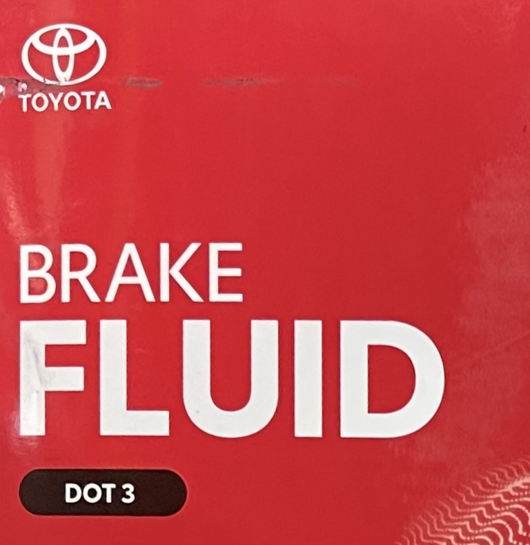
Brake Fluids
These are fluids have very high boiling points and very low freezing points are generally Glycol based. They are hydroscopic which means that can they absorb moisture.. Should you get a message on your dashboard that your brake fluid is low ensure that you top up with the fluid specified by the manufacturer. Should this reoccur have your brake system checked it probably has a leak in the system.
Take care not to spill any fluid onto painted surfaces as it can damage theses surfaces wash off immediately with water.
Purpose
Their purpose is to remain as liquids, and not to boil despite being exposed to very high temperatures arising from the friction between the rotors and the brake pads.
Description
Every manufacturer specifies the specific brake fluid to be used of each model they produce. It is critically important that only the specified brake fluid be used. The fluid should be replaced at least every two years 40000 klms or whenever the water moisture lever approaches or exceeds 2%. Liquids cannot be compressed air can. Should there be any air in the system this renders the whole system becomes inefficient and the brakes feels soft and spongy.
When going down a long incline should the brakes start feeling spongy, this is an indication that your brake fluid needs changing. Take greater care and allow for longer stopping distances. If possible stop for while for the fluid to cool down. Should the brakes once again feel firm you can be fairly confident that the problem is the brake fluid. To be sure have it professionally diagnosed.
Brake Fluid Exchange
Brake Fluid is Hydroscopic. Respite efforts to seal off the brake fluid contamination of the brake fluid by moisture some does get into the fluid.
Purpose
The purpose is to completely remove the old contaminated brake fluid and replace it with fresh brake fluid.
The water in the hydraulic system will corrode the cylinder bores and pistons overtime , this will create leaks and brake failure.
The boiling point of pure brake fluid is higher that the boiling of water. This is to inhibit the brake fluid reaching boiling point. When the brake fluid has absorbed water the boiling is lowered. The brake fluid containing moisture can then boil when the heat from the brake pads is conducted through the brake pad backing plate through the piston to the fluid. The brake fluid will create air bubbles within the system. You might have observed this at home seeing a pot of water boiling on a cooktop when air bubbles rise through the water.
Liquids do not loose volume when compressed. Air does.
This air in the brake system makes the brake pedal feel spongy and inhibits the efficient operation of the braking system.
The brake fluid should have no more than 2% moisture after 2 years . Most manufacturers of brake fluid recommend the brake fluid should be renewed.
Description
Most of the old brake fluid in the master cylinder reservoirs should be syphoned out and filled with new brake fluid. Then one wheel at a time a clear plastic tube should be attached to the bleed nipple the other end into a waste container. The bleed nipple opened. One would pressurise the master cylinder reservoir so that when the bleed nipple is opened the new fluid would force the old fluid before it until the new fluid comes out of the bleed nipple. As soon as the fresh fluid exits the bleed nipple it should be tightened.
In between bleeding each wheel one must refill the brake fluid reservoir. You definitely do not want to pump air through the brake master cylinder into the brake lines. One would continue the follow this procedure on the remaining three calipers.
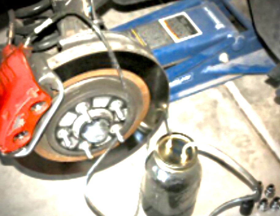
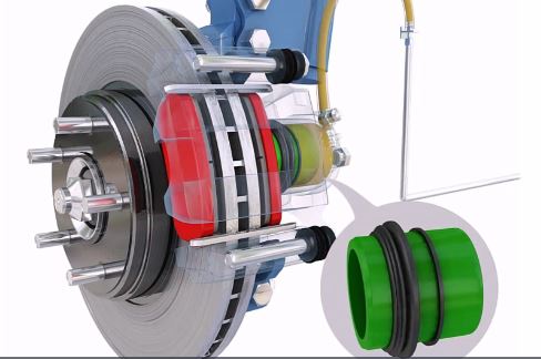
The Brake Calliper
The brake calliper is attached to the wheel hub. On average the pistons housed within the calipers are about 75mm from the outer edge of the rotor.
Purpose
As the wheel is steered left or right so too does the calliper move with it. The brake rotor also attached to the wheel hub so that the rotor and brake calliper move in union with each other. The calliper sits over the outer edges of the rotor. The calliper houses the calliper pistons. The brake pads sit between the calliper pistons and the rotor. The callipers are attached to the steering knuckle and swivel with the wheels as they move. The brake callipers are “u” shaped through which the rotors can rotate freely.
Description
The brake pads are held on sliders so that as the brake is applied the brake pads are able to move along the sliders. This forces the piston into contact with the brake pads and then on to the rotor. The calliper shown above pushes against the pads on one side only, resulting to uneven wear of the opposing pad and rotor against it pushes.
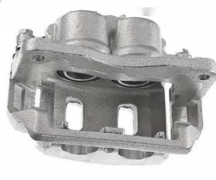
To overcome this problem callipers are also made with active pistons on either side of the calliper. These in turn force both the brake pads simultaneously on to either side of the rotor. These are called Twin Spot Callipers. Those with two pistons on each side 2 Spot and those with four on either side 4 Spot.
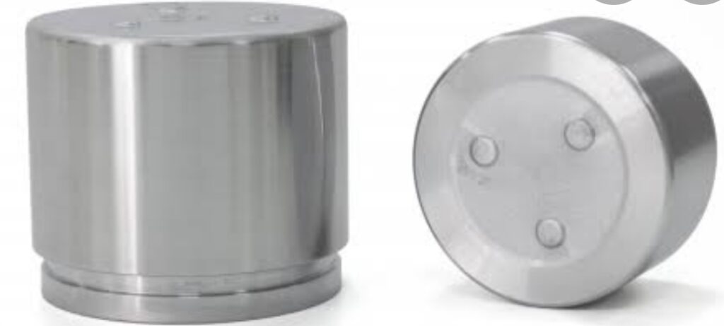
Brake Calliper Pistons
Brake calliper pistons are hollow and open at one end. They slide back and forth in the brake calliper.
Purpose
The function of the calliper is to transfer the hydraulic pressure in the brake lines into physical movement and push on to the metal backing of the brake pad.
The piston in the calliper is pushed forward forcing the brake pads up against the brake rotor. The harder that the driver presses on the brake pedal the greater is the friction between the brake pads and the brake rotors. This huge friction is transferred via the wheel rims to the surfaces of the tyres where they make contact with the road causing the vehicle to slowdown.
Description
Previously brake pistons were made from metal with stainless steel or chrome finish. The latest innovation is that they are now from phenolic resin which is lighter, does not corrode and has lower heat transfer of heat from the brake pad to the brake fluid. These phenolic resin pistons cannot be substituted for the old metallic type. phenolic resin phenolic resin. The pistons sit behind dust boots to protect them from dust and dirt from the road which would grind their surfaces creating leaks and poor braking.
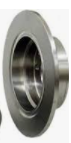
Brake Rotors
Brakerotors are flat metal discs having their centre portion protruding to attach, with wheel bolts, the wheel hub.
Purpose
Brake rotors are the final stage in the braking system.
Description
The brake discs need to be made out of extremely strong metal. On their vertical surfaces near their outer edges are subjected to huge pressures. They ultimately must bear the weighted momentum of the car to a complete stop. From a side on view they look like a hat with a raised centre portion which is bolted to the wheel hub and rotate with the wheel and tyre. In addition to the huge pressure they a subjected to enormous heat generated by the friction when the brake pads are forced on to the rotating rotors. When driving down a long incline the heat generated can cause the metal to discolour and warp.
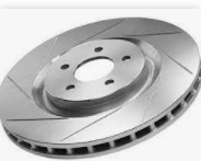
There are variations on the solid smooth surfaces to attempt to cool the rotors.
Some have trailing grooves cut into their surfaces. Other have holes drilled from side to side through the metal vertical surface. Yet other have a combination of hole and slots as shown above.
On some cars slotted discs are now being used. Looking down the vertical face from the top you will observe that the inner and outer edge of wall is not solid right through. There are a number of walls separating the two walls with large air gaps running from the outer edge to the inner core of the brake rotor. These channels draw air in and through the heated metal drawing as much heat bas possible from the rotor. These are called vented rotors.
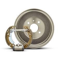
Brake Drums
Purpose
Brake drums too are the final stage in the braking system.
Description
Whereas brake rotors have their braking surfaces in a vertical plane brake drums are concave and their braking surfaces are at 90 degrees to vertical. The stopping action is created by two metal curved brake shoes to which are riveted the brake lining friction material. The shoes are pivoted at one end. Between the other two ends is an extendable cylinder. As the brakes are applied the pressure of the brake fluid forces the two free ends apart shoes onto the wall of the drum. The brake drums are attached to the wheels and thus force the car to slow down and stop.
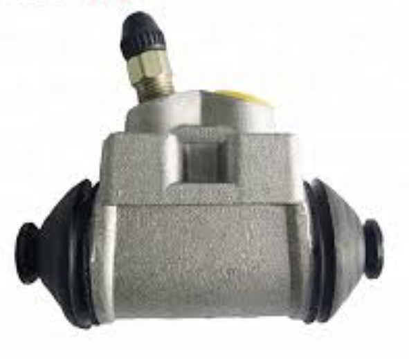
Wheel Cylinders
Purpose
Is to expand two arms outward to force the brake shoe linings against the brake drum the slow and stop the vehicle.
Description
A B is a component of a hydraulic brake drum system. It is usually located on the backing plate on the top above the brake shoes . Its function is to use hydraulic pressure to exert force onto the shoes so that the brake friction material comes into contact with the drum and stops the vehicle. The wheel cylinders are usually connected to the shoes with small bird-beak shaped rods. Wheel cylinders were first invented by Bendix in 1958.
Internally consisting of only pistons, seals and springs, some types also included valves. On older vehicles, these tended to begin leak and hinder the performance of the brakes. They are, however, normally inexpensive and relatively reliable.
When hydraulic brake pressure is applied, the pistons are forced out when the pressure is released the brake shoe return spring pull the shoes back to a relaxed position pushing the pistons back and the fluid needs to flow back into the master cylinder , the master cylinder needs to match a brake shoe cylinder set up as the master cylinder has a valve to keep a small residual pressure in the brake lines so that there is no delay activating the cylinder to shoe contact. Some designs use two single piston wheel cylinders, one at the top of the drum and one at the bottom, each connected to one brake shoe.
Wheel cylinders must be replaced if they show signs of leaking. Wheel cylinders used to be made of cast iron. However, they were more prone to rusting and aluminum is now the preferred material. The cast iron designed cylinder could be rebuilt, and some of the hard to source aluminum cylinder can be re manufactured the cylinder needs to be bored to a larger diameter and then a stainless steel sleeve inserted into the bore .Cut and honed . This is a very expensive process.
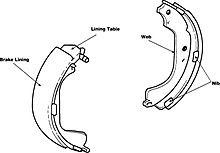
Brake shoes
Brake shoes are mostly constructed of two pieces of metal welded together. The friction material is either riveted or bonded in an oven with adhesive to the web face. There is a half moon shaped section that has holes and slots cut out to mate to the wheel cylinder and pivot blocks and cross rods and springs both for return and self adjusting components
The hydraulic force of the wheel cylinder is applied to shoe and lining to the inside surface of the brake drum The edge of the web has tabs on each side called nibs. The nibs rest against the support pads of the backing plate to which the shoes are installed. these touch points can be noisy if not lubricated. Each of the shoes have a primary and secondary.
Mostly the primary shoe is located toward the front of the vehicle and has the lining positioned differently from the secondary shoe. Linings must be resistant to heat and wear and have a high coefficient of friction unaffected by fluctuations in temperature and humidity.
Materials that make up the brake shoe lining include friction modifiers (which can include graphite and cashew nut shells), metals such as lead, zinc, brass, aluminum and other metals that resist heat fade, binders, and fillers such as rubber chips to reduce brake noise.
Drum brakes were used in older style cars for front brakes and are still used in trucks Drum brakes in modern cars are sometimes fitted to the rear wheels since most of the stopping force is generated by the front brakes of the vehicle and therefore the heat generated in the rear is significantly less. Drum brakes allow simple incorporation of a parking brake.
Drum brakes are also occasionally fitted as the parking (and emergency) brake even when the rear wheels use disc brakes as the main brakes. Many rear disc braking systems use a parking brake in which the piston in the caliper is actuated by a cam or screw. This compresses the pads against the rotor. This type of system becomes much more complicated. Especially when the park brake is controlled electronically.
The electronic park brakes often need a computer to be connected to the car to release the park brake before brake pads can be replaced. When connecting a computer and driving the rear brake motors it is always advisable to supply the vehicle with a stable voltage supply acting like an alternator even though the engine is not running.
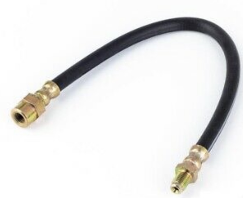
The Flexible Hose
This hose is a high pressure hose.
Purpose
This cushions the movement between the static chassis of the car and the movement of the wheel hub assembly and braking assembly.
Description
This is a short maybe 25cms long flexible hose with external wire braiding and connectors at each end to connect to the brake pipes and calliper.
Brake Proportioning valve
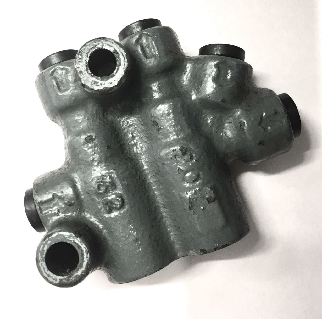
Sits in between the brake master cylinder and the callipers in the wheels is the break proportioning valve.
Purpose
It divides the pressurised brake fluid from the master cylinder and proportions it appropriately depending to which wheel it is going. Not present in vehicles fitted with ABS.
The pressurised fluid must not exert the same pressure to all four wheels simultaneously.
Description
The front two wheels do receive equal pressure brake fluid to their callipers. The rear two wheels lesser than the front wheel.
More pressure is applied to the front wheel brake callipers as they are responsible for more of the braking effort than the rear. This division is controlled by the proportioning valve.
The front brakes of the vehicle need to absorb more of workload for stopping than the rear brakes. The proportioning valve controls this subdivision. Balance between front brakes. Front minimum 55% to maximum 90% and rear brakes minimum 10% and maximum 45%. This is to reduce the effect of rear brakes locking up.
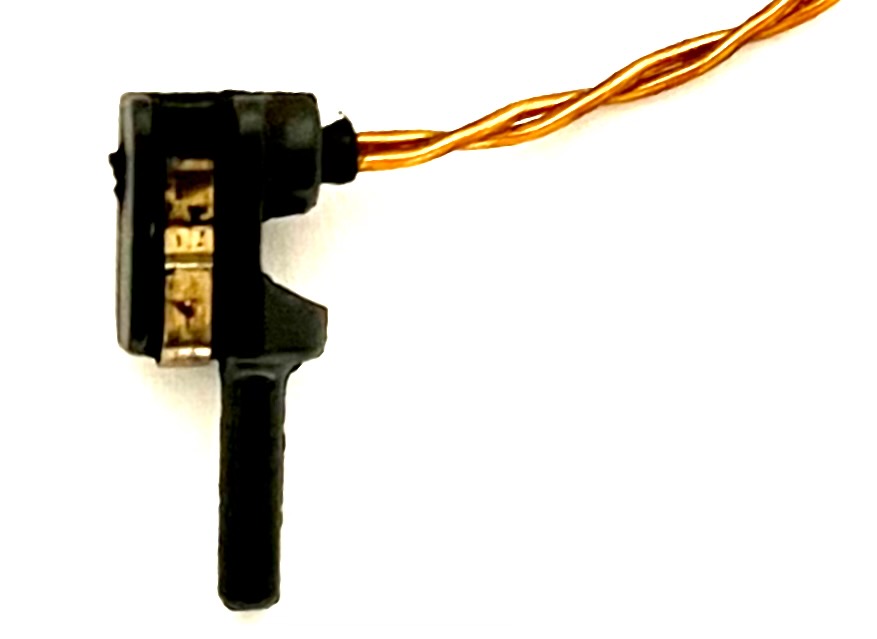
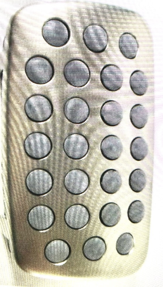
Brake Wear Sensors
These come in various technologies their function is to warn drivers that the brake pads are coming to the end of their effective usage.
The brass clips in the picture above fit into a slot in the metal backing of the brake pad. The vertical column beneath it fits into the brake pad right next to the metal backing. As the brake pad wears the sensor will eventually come into contact with the rotor. This will trigger a signal on the dashboard that the brakes need attention. Sometimes the messages say your brake pads need attention. This is very misleading as it is often interpreted as meaning pads only. The pads as well as the rotors are wearing parts rubbing against each other, invariably Both need to be changed at the same time.
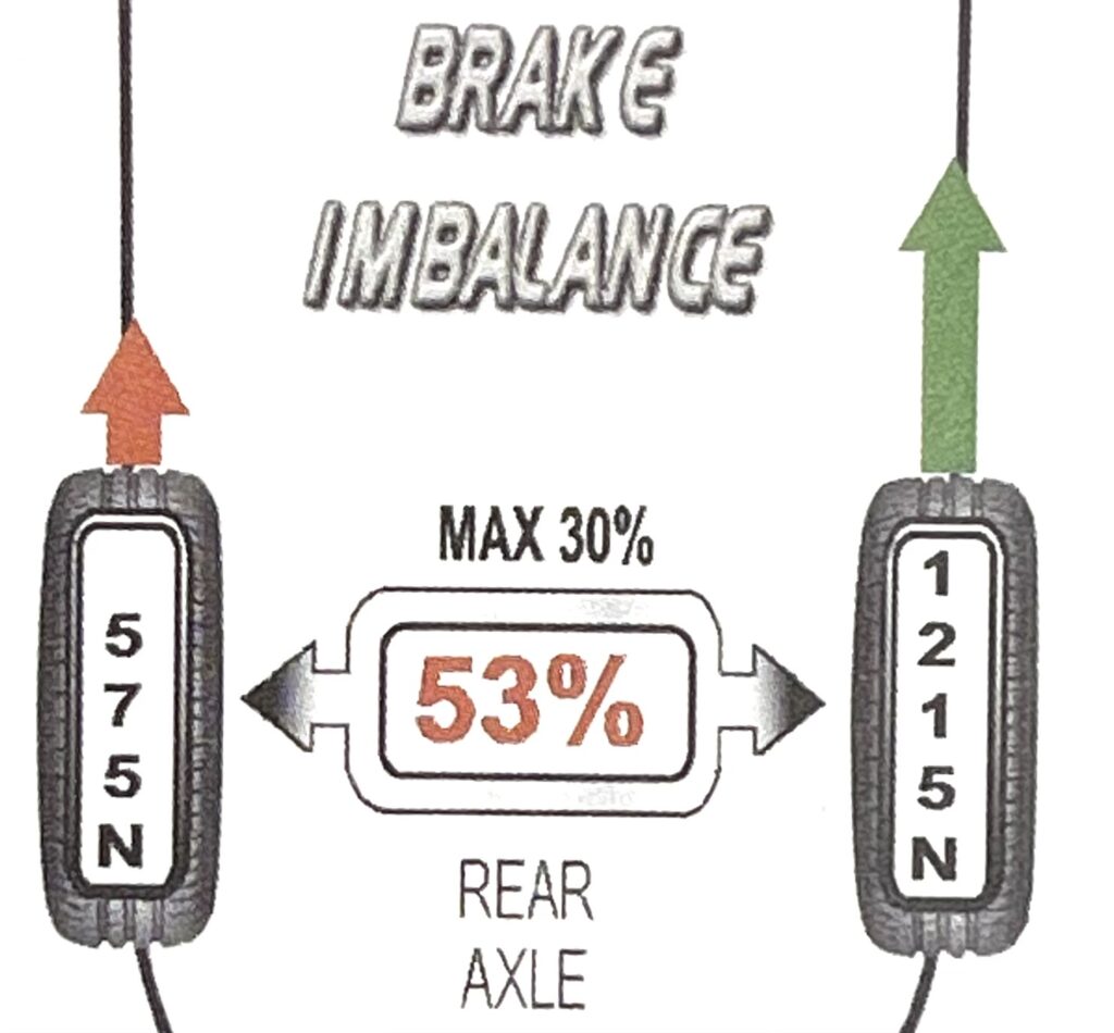
“Anti lock Braking Systems” (ABS)
This gives the driver far greater control of the car in emergency stopping situations.
Wheels can lock up when hard braking is applied the tyres would skidded across the road surface. As steering is based on the rotation of the tyres on the road and the tyres were no longer rotating one loses all steering control.
The ABS (Anti Lock-braking System) sensors are continuously monitoring the speed rotation of each wheel. When there is an imbalance between the speed of wheel rotation,front pair or rear pair, or when the wheels lockup, the ABS is activated. Even with the drivers foot hard on the brake pedal, many times per second the braking is released and reapplied. The friction between road and tyre is actually increased making stopping distance shorter and of equal or greater importance is the driver does not loose steering control.
RECENT POSTS & TIPS
- Cross Section Of A Typical Water Themostat
- Testing of EV AC Electric Motor Phase Resistance Balance Test of The Windings
- Brake Fade
- Instructions for Jump Starting a Car
- Low-Pressure Exhaust Recirculation Filter (ERF)
- Reasons for front wheel bearings to breakdown
- Brake Cylinders Failure - Detection & Consequences
- Pollen Filters
- Will a DPF regeneration cure the blocked exhaust issue?
- Why should I change the oil filter each time I change the engine oil in my car?
- What Is AdBlue ?
- Origins of Suspension Systems for Modern Vehicles
- Parasitic Battery Drain
- ELECTRIC VEHICLES – A SIMPLE EXPLANATION
- GIL’S FORESIGHT, ELECTRIC VEHICLES WERE COMING
- MECHANICS OF VARIOUS BRAKE SYSTEMS
- SCAN TOOLS DO NOT FIX CARS. HIGHLY QUALIFIED MECHANICS DO.
- TOYOTA PRIUS HYBRID BATTERY REPAIR
- DIAGNOSING A FAULTY FUEL PUMP
- NEW TYRES FITTED OR WHEELS ROTATED
